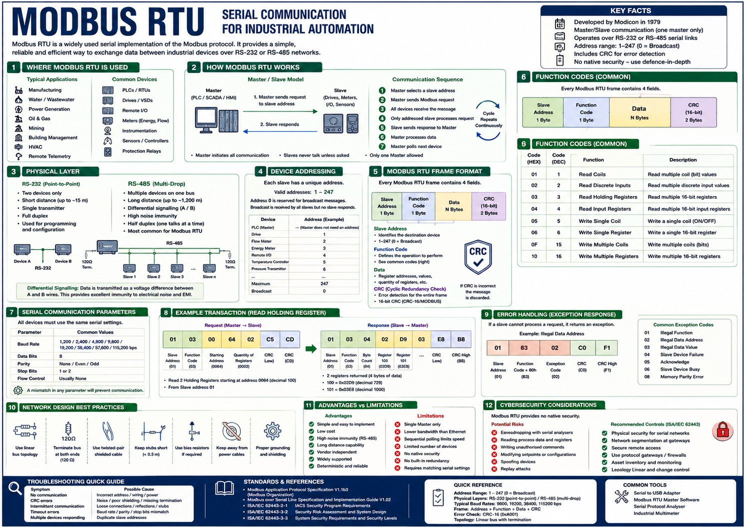
Modbus RTU (Remote Terminal Unit) is the most common serial implementation of the Modbus protocol. Developed by Modicon in 1979, it provides a simple, efficient, and reliable method of exchanging data between industrial devices over serial communication links.
Unlike Modbus TCP, which operates over Ethernet networks, Modbus RTU transmits binary data over serial interfaces such as RS-232 and, more commonly, RS-485. It is widely used in Industrial Automation and Control Systems (IACS) because of its simplicity, deterministic behaviour, and compatibility with a vast range of industrial equipment.
Today, Modbus RTU remains common in legacy facilities and is frequently used to connect PLCs, Remote Terminal Units (RTUs), variable speed drives, power meters, protection relays, intelligent instrumentation, and remote I/O systems.
Modbus RTU is found throughout industry, particularly where simple and reliable communications are required over relatively short distances.
Common applications include:
Typical connected devices include:
Modbus RTU uses a Master/Slave communication model (also referred to as Client/Server in modern terminology).
The Master controls all communications by sending requests to individual slave devices. Slave devices never initiate communication; they only respond when addressed by the Master.
Only one Master is permitted on a Modbus RTU network. This deterministic communication model prevents collisions and simplifies troubleshooting.
Modbus RTU commonly operates over RS-485, although it can also use RS-232 for point-to-point communication.
RS-232 supports communication between two devices only.
Characteristics:
Typical applications:
RS-485 is the preferred physical medium for Modbus RTU. It supports:
RS-485 is specifically designed for harsh industrial environments where electrical noise, long cable runs, and multiple field devices are common.
Unlike Ethernet, RS-485 does not transmit data relative to ground.
Instead, it transmits the voltage difference between two conductors:
The receiving device compares the voltage difference rather than the absolute voltage level. This greatly improves immunity to:
This is one reason Modbus RTU remains popular in industrial environments.
Modbus RTU networks should be wired as a single linear bus.
Typical architecture:
Master PLC
     │
============================ RS-485 ============================
     │              │             │             │
   Drive         Flow Meter    Energy Meter   Remote I/O
Each device connects directly to the main communication cable. Long spur connections should be avoided as they can introduce signal reflections and communication errors.
Each slave device is assigned a unique address.
Valid addresses: 1–247
Address 0 is reserved for broadcast messages. Broadcast messages are received by every slave device, but no slave sends a response. This prevents multiple devices from transmitting simultaneously and causing collisions.
| Device | Address |
|---|---|
| PLC | 1 |
| Drive | 2 |
| Flow Meter | 3 |
| Energy Meter | 4 |
| Remote I/O | 5 |
Communication follows a simple request-response cycle.
This cycle repeats continuously. Because only one device transmits at a time, collisions are avoided.
A Modbus RTU message contains four main fields.
| Field | Description |
|---|---|
| Slave Address | Identifies the destination device |
| Function Code | Specifies the requested operation |
| Data | Registers, values, or parameters |
| CRC | Cyclic Redundancy Check used for error detection |
Unlike Modbus TCP, there is no MBAP header because serial communications do not require TCP/IP addressing.
Every Modbus RTU frame ends with a 16-bit Cyclic Redundancy Check (CRC).
The receiving device recalculates the CRC and compares it with the transmitted value. If the CRC values differ, the message is discarded.
This mechanism detects:
The CRC improves communication reliability but does not provide cybersecurity or protect against intentional message modification.
All devices on the network must use identical communication settings.
| Setting | Common Values |
|---|---|
| Baud Rate | 9,600 / 19,200 / 38,400 / 115,200 bps |
| Data Bits | 8 |
| Parity | None, Even, Odd |
| Stop Bits | 1 or 2 |
A mismatch in any parameter prevents successful communication.
A reliable Modbus RTU network requires careful installation.
Best practices include:
Incorrect wiring is one of the most common causes of communication failures.
Modbus RTU was designed for isolated industrial networks and provides no native cybersecurity mechanisms. The protocol does not support:
If an attacker gains physical access to the serial network, they may be able to:
Although remote attacks are less common than with Ethernet-based protocols, Modbus RTU networks remain vulnerable when connected to gateways, terminal servers, or protocol converters that bridge serial networks to IP networks.
ISA/IEC 62443 recommends protecting legacy serial networks through defence-in-depth measures such as physical security, network segmentation at protocol gateways, secure remote access, industrial firewalls, asset inventory, and continuous monitoring of connected systems.
Common causes of Modbus RTU communication failures include:
| Symptom | Possible Cause |
|---|---|
| No communication | Incorrect slave address |
| CRC errors | Electrical noise or poor cable shielding |
| Intermittent communication | Missing termination resistors |
| Timeout errors | Baud rate or parity mismatch |
| Multiple devices responding | Duplicate slave addresses |
| Random communication failures | Star topology or excessive cable stubs |
Systematic verification of wiring, serial parameters, addressing, and cable integrity is typically the first step in diagnosing Modbus RTU issues.