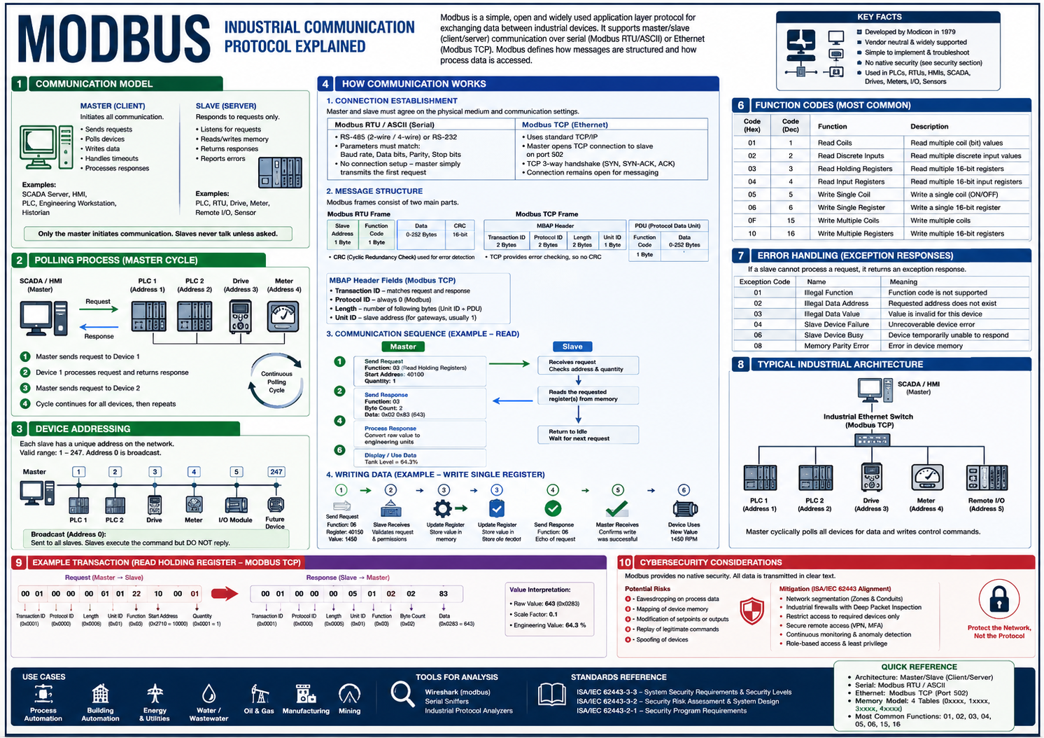
Modbus is an application-layer communication protocol developed by Modicon (now Schneider Electric) in 1979 for industrial automation systems. It provides a standard method for exchanging data between controllers, field devices, Human Machine Interfaces (HMIs), Supervisory Control and Data Acquisition (SCADA) systems, and engineering workstations.
Modbus itself does not define the physical communication medium. Instead, it defines how devices structure messages and exchange information. The protocol can operate over serial communication (Modbus RTU and Modbus ASCII) or Ethernet (Modbus TCP).
The primary purpose of Modbus is to allow one device to request information from another or instruct another device to change a value.
Traditional Modbus uses a Master/Slave architecture. Modern terminology replaces these terms with Client/Server, although both are commonly encountered in industrial documentation.
The master controls all communication. Its responsibilities include:
Typical masters include:
Only the master can begin communication.
Slave devices never initiate communication. Instead they simply wait for requests.
Their responsibilities include:
Typical slave devices include:
A slave only communicates after receiving a valid request.
Modbus is a polling protocol. The master continuously asks each device whether new information is available.
For example:
Master → PLC 1    "Read Tank Level"
PLC 1  → Master   "Tank Level = 67%"
The master then immediately polls the next device.
Master → PLC 2    "Read Pump Status"
PLC 2  → Master   "Pump Running"
Then:
Master → PLC 3 "Read Pressure"
This cycle repeats continuously. A SCADA system may perform hundreds or even thousands of polls every second depending on the number of connected devices.
Each Modbus slave has a unique address.
Typical address range: 1–247
Address 0 is reserved for broadcast messages. Broadcast messages are processed by every slave but no slave sends a reply, preventing multiple devices from transmitting simultaneously.
| Device | Address |
|---|---|
| PLC 1 | 1 |
| PLC 2 | 2 |
| Drive | 3 |
| Flow Meter | 4 |
| Remote I/O | 5 |
When the master sends a request to Address 3, only the drive responds.
One of Modbus' greatest strengths is its simple and standardised memory model. Instead of accessing variables by name (such as Tank_Level or MotorSpeed), Modbus reads and writes predefined memory locations. These memory locations are organised into four logical tables.
Coils represent single-bit outputs. Each value is either ON or OFF.
Typical examples include:
Read/Write access.
Discrete Inputs are single-bit values that represent physical inputs.
Examples include:
Read Only.
Input Registers store analogue measurements.
Examples include:
Each register contains 16 bits. Read Only.
Holding Registers are the most commonly used Modbus memory area. They can contain:
Read/Write. Most PLC communications primarily involve Holding Registers.
Suppose a SCADA system needs to display a tank level. The tank level is stored inside Holding Register 40100.
Step 1 — The SCADA sends a request:
Read Holding Register
Address: 40100
Quantity: 1
Step 2 — The PLC receives the request and looks up Register 40100 inside its memory:
40100 = 643
Step 3 — The PLC returns the value:
643
Step 4 — The SCADA converts the engineering value. Perhaps:
643 = 64.3%
The operator now sees:
Tank Level 64.3%
Writing follows a similar process. Suppose an operator changes the pump speed.
Current speed:  1200 RPM
New speed:      1450 RPM
The HMI sends:
Write Holding Register
Register = 40150
Value    = 1450
The PLC receives the request, updates Register 40150, returns confirmation, and the PLC program now uses the new value.
Every Modbus request begins with a Function Code. The Function Code tells the slave what operation should be performed.
| Function Code | Operation |
|---|---|
| 01 | Read Coils |
| 02 | Read Discrete Inputs |
| 03 | Read Holding Registers |
| 04 | Read Input Registers |
| 05 | Write Single Coil |
| 06 | Write Single Holding Register |
| 15 | Write Multiple Coils |
| 16 | Write Multiple Holding Registers |
These eight function codes account for the majority of Modbus communications in industrial systems.
The following illustrates a complete transaction between a SCADA system and a PLC.
SCADA                          PLC
  │                              │
  │  Read Holding Register 40120 │
  │─────────────────────────────►│
  │                              │  Looks up Register
  │                              │  Value = 725
  │◄─────────────────────────────│  Returns Value
  │                              │
SCADA displays: 72.5°C
Each request receives one response before the next request is sent, making Modbus deterministic and straightforward to troubleshoot.
If the PLC cannot complete the request, it returns an Exception Response instead of the requested data.
| Exception | Description |
|---|---|
| Illegal Function | The function code is not supported by the device. |
| Illegal Data Address | The requested register does not exist. |
| Illegal Data Value | The supplied value is outside the valid range. |
| Slave Device Failure | The device encountered an internal error while processing the request. |
| Slave Device Busy | The device is temporarily unable to process the request. |
These exception codes help SCADA systems detect communication issues and alert operators to configuration or device problems.
A common Modbus deployment in an Industrial Automation and Control System (IACS) may resemble the following:
SCADA Server
      │
Industrial Switch
      │
┌─────┼─────┬──────────────┐
│     │     │              │
PLC 1 PLC 2 Energy Meter
│     │     │
Remote I/O  Drives  Power Monitoring
│
Sensors & Actuators
The SCADA server cyclically polls each device for process values, alarm states, and equipment status. Operators interact with the SCADA system rather than communicating directly with field devices.
Modbus remains one of the most widely used industrial protocols because it is:
Its longevity means it is still common in brownfield facilities and continues to be encountered in modern industrial networks.
Modbus was developed long before cybersecurity became a design consideration. Consequently, the protocol provides no native security features. Messages are transmitted in clear text, with no authentication, encryption, or integrity protection.
This allows an attacker with network access to:
Because of these limitations, ISA/IEC 62443 does not rely on Modbus itself for security. Instead, it recommends protecting Modbus communications through defence-in-depth measures such as security zones and conduits, industrial firewalls with deep packet inspection (DPI), network segmentation, secure remote access, continuous monitoring, and strict access control.
While ISA/IEC 62443 does not define Modbus, its secure deployment is addressed through system-level requirements, particularly: